True bypass & LED mod for GCB-95

  • Thread starter copperheadroad
  • Start date
  • This site may earn a commission from merchant affiliate links like Ebay, Amazon, and others.

copperheadroad

Senior Member
Joined
Feb 7, 2010
Messages
1,380
Reaction score
576
I have GCB-95 rev c (the one without pcb mounted jacks) & I wanted to do the true bypass mod & add a LED & I'm not sure where to wire them on the board.
I see quite a few instructions on how to do this on the newer models but not the rev c
It has the same board as in this pic
 

RambleFX

Senior Member
Joined
Dec 28, 2011
Messages
464
Reaction score
516
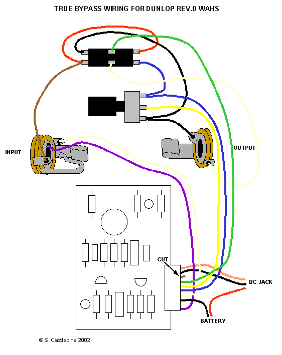
Time to start tracing the circuit to find the input, output, 9V power, and ground connections. You will need to replace the DPDT footswitch with a 3PDT switch because you need an extra pole to switch the LED on/off. The 10 pin connector makes it hard to make a clean connection to the board, so you'll want to splice into the wires.

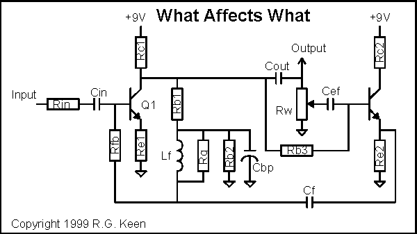
If you need help, photograph the top and bottom of the board and post the pics here. Below is a wiring diagram and a schematic that should help.

wah8.gif

StompboxWiring.gif
 

copperheadroad

Senior Member
Joined
Feb 7, 2010
Messages
1,380
Reaction score
576
Thanks.... I will get some pics up right away
I do have the 3PDT switch
 

RambleFX

Senior Member
Joined
Dec 28, 2011
Messages
464
Reaction score
516
Through the magic of Photoshop...

This looks like it already is true bypass. Isn't that a 6 lug, DPDT footswitch? Pull the power while it is in bypass, do you still get your bypassed tone?
 

Attachments

  • GCB95 rev C.jpg
    GCB95 rev C.jpg
    95.2 KB · Views: 277

Batman

Senior Member
Joined
Nov 10, 2011
Messages
6,711
Reaction score
7,029
Copperhead, I've done the true bypass version of this mod on the exact same Crybaby. Unfortunately, I'm not home but if you can wait until Monday, I have my notes at home on exactly what I did.

When you do the mod you will probably need to do the volume and gain mods. . .i noticed a significant drop in output after converting mine.

Give me a bit, I'll see if I can find the Internet instructions I used in the interm.
 

Batman

Senior Member
Joined
Nov 10, 2011
Messages
6,711
Reaction score
7,029
Try here Castledine Electronics - Guitar Effects under DIY Resources --> True Bypass Mod. I used the directions for the Rev D board. . .Rev C and D are supposed to be identical for the purpose of this mod.

The volume and gain mods are on the Wah Circuit Mods page.

HTH
 

copperheadroad

Senior Member
Joined
Feb 7, 2010
Messages
1,380
Reaction score
576
Through the magic of Photoshop...

This looks like it already is true bypass. Isn't that a 6 lug, DPDT footswitch? Pull the power while it is in bypass, do you still get your bypassed tone?

The first pic i posted is NOT my wah but the same with true bypass mod done (I think but not sure )

No my switch only has only 3 lugs
 

copperheadroad

Senior Member
Joined
Feb 7, 2010
Messages
1,380
Reaction score
576
Copperhead, I've done the true bypass version of this mod on the exact same Crybaby. Unfortunately, I'm not home but if you can wait until Monday, I have my notes at home on exactly what I did.

When you do the mod you will probably need to do the volume and gain mods. . .i noticed a significant drop in output after converting mine.

Give me a bit, I'll see if I can find the Internet instructions I used in the interm.

I have already modded with those mods (I believe) I have to recheck what I've done ,Its been over a year since I've done it
thanks
 

Beerdog80

Banned
Joined
May 12, 2008
Messages
10,958
Reaction score
5,681


This should set you up. You don't HAVE to use a 3PDT switch for an LED since you have a problem with your board already. These boards (w/o the 9v adaptor and jacks on the them) also don't have polarity protection and extra filtering built in as the later models do.

Problem there is you might get some 'bumps' when you engage it since the filter cap found on the other revisions isn't there to eat that up for you. You can give it a shot on yours to see if you get those 'bumps' (it's been a LONG time since I've toyed with that revision so I can't tell you for sure yes/no).

Just steal 9v power from the positive and return it to the negative of the resisters you already indicated. With the limiting resister in place, you will get light...bumps might optional unless you add another filter cap.
 

copperheadroad

Senior Member
Joined
Feb 7, 2010
Messages
1,380
Reaction score
576
Yes I have the 3PDT switch ,I've seen this diagram ,So how will I wire it to to the 3PDT switch along with the led ?
If you were referring to the first photo It has the tru bypass done & it is just a photo i grabbed off google ,& not my actual pedal
 

RambleFX

Senior Member
Joined
Dec 28, 2011
Messages
464
Reaction score
516
Here's the rest of the labels. There is a reverse polarity protection diode (1N4148) in the bottom right corner and a DC filter cap right above it. If you want an LED, you need a 3PDT. There are ways around that, but they require extra circuitry and are more complex. Now that everything is identified, you should be able to follow the standard stompbox wiring using the pic I posted above.

There are a couple ways you can power it. I would use the left V+ as the power connection and then the right V+ can be a direct connection to an LED because the power goes through a 1.5K resistor.

Hopefully that makes sense. With everything labelled you should be able to follow the schematic to figure everything out.

CrybabyWahrevC.jpg
 

JJP

Junior Member
Joined
Jul 25, 2013
Messages
1
Reaction score
0
I have a Crybaby Wah model GCB Rev C exactly like the picture above. I am doing some mods and bought a Yellow Fasel inductor. I've noticed the original inductor has 6 pins and the Yellow Fasel only has two. My question is, through which two holes does the Fasel get soldered to on my PCB? Can anyone help? Thanks!
 

RambleFX

Senior Member
Joined
Dec 28, 2011
Messages
464
Reaction score
516
I have a Crybaby Wah model GCB Rev C exactly like the picture above. I am doing some mods and bought a Yellow Fasel inductor. I've noticed the original inductor has 6 pins and the Yellow Fasel only has two. My question is, through which two holes does the Fasel get soldered to on my PCB? Can anyone help? Thanks!
Look closely at the pic above. Each group of 3 are connected together. Just remove the old and solder to the most convenient spots.
 

Latest Threads


Top
')