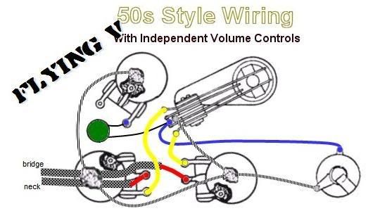
Help!!! Check out this wiring.

  • Thread starter kmasters68
  • Start date
  • This site may earn a commission from merchant affiliate links like Ebay, Amazon, and others.

kmasters68

Senior Member
Joined
Aug 6, 2015
Messages
1,328
Reaction score
365
So, I've check and double checked and can't figure out why its not working. I must be doing something wrong and I'm not getting it.

I go to GREAT LENGTHS to hide my soldering skills from public scrutiny:wow:, but in this case, I must swallow my pride and show you what the heck I have going on.:hmm:
 

Attachments

  • IMG_1426.jpg
    IMG_1426.jpg
    84.1 KB · Views: 110
  • IMG_1421.jpg
    IMG_1421.jpg
    85.7 KB · Views: 119

kmasters68

Senior Member
Joined
Aug 6, 2015
Messages
1,328
Reaction score
365
I also tried switching the tone around, like this:
 

Attachments

  • IMG_1430.jpg
    IMG_1430.jpg
    89.1 KB · Views: 85

Cjsinla

Senior Member
Joined
Jul 7, 2014
Messages
5,395
Reaction score
5,253
My V has the same wiring, yours looks pretty good. Have you tried a continuity tester to check for shorts?
 

kmasters68

Senior Member
Joined
Aug 6, 2015
Messages
1,328
Reaction score
365
So it looks correct? I tried replacing the toggle harness thinking it might have fatigued. I'm at a loss. I've spent 5-6 hours on this thing! I'm not sure how to check continuity...
 

CheopisIV

Copper Slinger
MLP Vendor
Joined
Apr 15, 2010
Messages
3,658
Reaction score
3,293
Are your Blue and Black grounded at the switch? Middle should go to output direct and tone before the cap... hmm, looks like they do.
wiringV50sInd.jpg
 

Kris Ford

Senior Member
Joined
Dec 17, 2011
Messages
4,751
Reaction score
4,127
I would do the following..
Check the connection from the bent up lug to the pot casing..

Check all the wires that go to the JACK, including from the switch.
 

kmasters68

Senior Member
Joined
Aug 6, 2015
Messages
1,328
Reaction score
365
I would do the following..
Check the connection from the bent up lug to the pot casing..

Check all the wires that go to the JACK, including from the switch.

I did that. A visual check at least. I guess I could re-solder the jack... I guess I'm at least justified that my wiring isn't wonky.
 

ReWind James

ReWind Electric Pickups Gear & Instrument Services
Double Platinum Supporting Member
Joined
Mar 11, 2009
Messages
22,065
Reaction score
39,834
I also tried switching the tone around, like this:

This photo makes it look as if the cap lead may be shorting the middle lug to ground. Also, what the others said.
 

kmasters68

Senior Member
Joined
Aug 6, 2015
Messages
1,328
Reaction score
365
This photo makes it look as if the cap lead may be shorting the middle lug to ground. Also, what the others said.

It does look like that, but its not touching. The input jack almost HAS to be the issue at this point, because I have basically tried ALL of the suggested wiring configs on the wiring library thread.
 

CheopisIV

Copper Slinger
MLP Vendor
Joined
Apr 15, 2010
Messages
3,658
Reaction score
3,293
A bad pot can wreak havoc on a good setup as well, do you have a multimeter to test things out? You can put the leads on the outer lugs to measure overall resistance and see if they're in spec, then put one on an outer and one on the middle to test the sweep. Doesn't matter which side but it should give a clean increase/decrease.
 

kmasters68

Senior Member
Joined
Aug 6, 2015
Messages
1,328
Reaction score
365
I had to table the project for a few days. I'll be back to it soon. The pots are newish and were juuuuust working before I dismantled.

sadly, I'm a novice at multimeters but have one. Will poke around with it after I desolder the jack.
 

CheopisIV

Copper Slinger
MLP Vendor
Joined
Apr 15, 2010
Messages
3,658
Reaction score
3,293
Check the pickups DC... are they the one's I sent you? They should read ~4.5k Neck and ~5k bridge if they're the Infernos. ;)
 

ARandall

Senior Member
Joined
Apr 16, 2012
Messages
18,470
Reaction score
17,763
A long shot, but maybe look at the switch to make sure the leaves are actually making good contact and there is continuity where there needs to be.
 

LeftyF2003

Senior Member
Joined
Mar 2, 2010
Messages
9,788
Reaction score
13,816
Without a tester you are blind. If you don't have one already get a multi meter and check all the connections that way. Re-soldering without testing may only introduce more problems. I got a cheap digital multi meter from some online place for $25.00 and it works fine. I would give you the manufacturer but there's nothing on it. Think China :laugh2:
 

kmasters68

Senior Member
Joined
Aug 6, 2015
Messages
1,328
Reaction score
365
I'll get my multimeter out next time I sit down to mess with it.
 

ReWind James

ReWind Electric Pickups Gear & Instrument Services
Double Platinum Supporting Member
Joined
Mar 11, 2009
Messages
22,065
Reaction score
39,834
You spent 5-6 hours on troubleshooting without a multimeter, even though you have one? I would re-think that approach.

Take a deep breath and start over with a clear mind and a meter. Go point by point. It's very possible that a pot or wire insulation could have been killed if you've soldered on it that much. Check every inch slowly and methodically. Use high heat briefly with your iron. Time on the work kills with soldering, not tip temperature.
 

kmasters68

Senior Member
Joined
Aug 6, 2015
Messages
1,328
Reaction score
365
I rebuilt the harness. I'll do testing today but it passed the "tap test". I'll string it up in a few hours.
 

kmasters68

Senior Member
Joined
Aug 6, 2015
Messages
1,328
Reaction score
365
Hey ho! I'm all straightened out now. Not sure what the problem was but I rebuilt it taking my time and viola! I even did the shielding paint while I was in there since this will be a high gain guitar. Not silent but VERY quiet even with the gain high!
 

Latest Threads


Top
')