Coil Split wiring for 50s Style Wiring in GFS pickups?

sebass

Junior Member
Joined
Mar 23, 2011
Messages
28
Reaction score
2
Hi guys. I'm rewiring my LP and want to pick your brains if my wiring is correct for 50s Style wiring with coil splitting in both pickups.

Also i can not rewire those pickups for Jimmy Page style 50s wiring due to missing 5th green cable correct?

GFS Kwikplug only has 4 wires total, not 5 like some other pickups have.

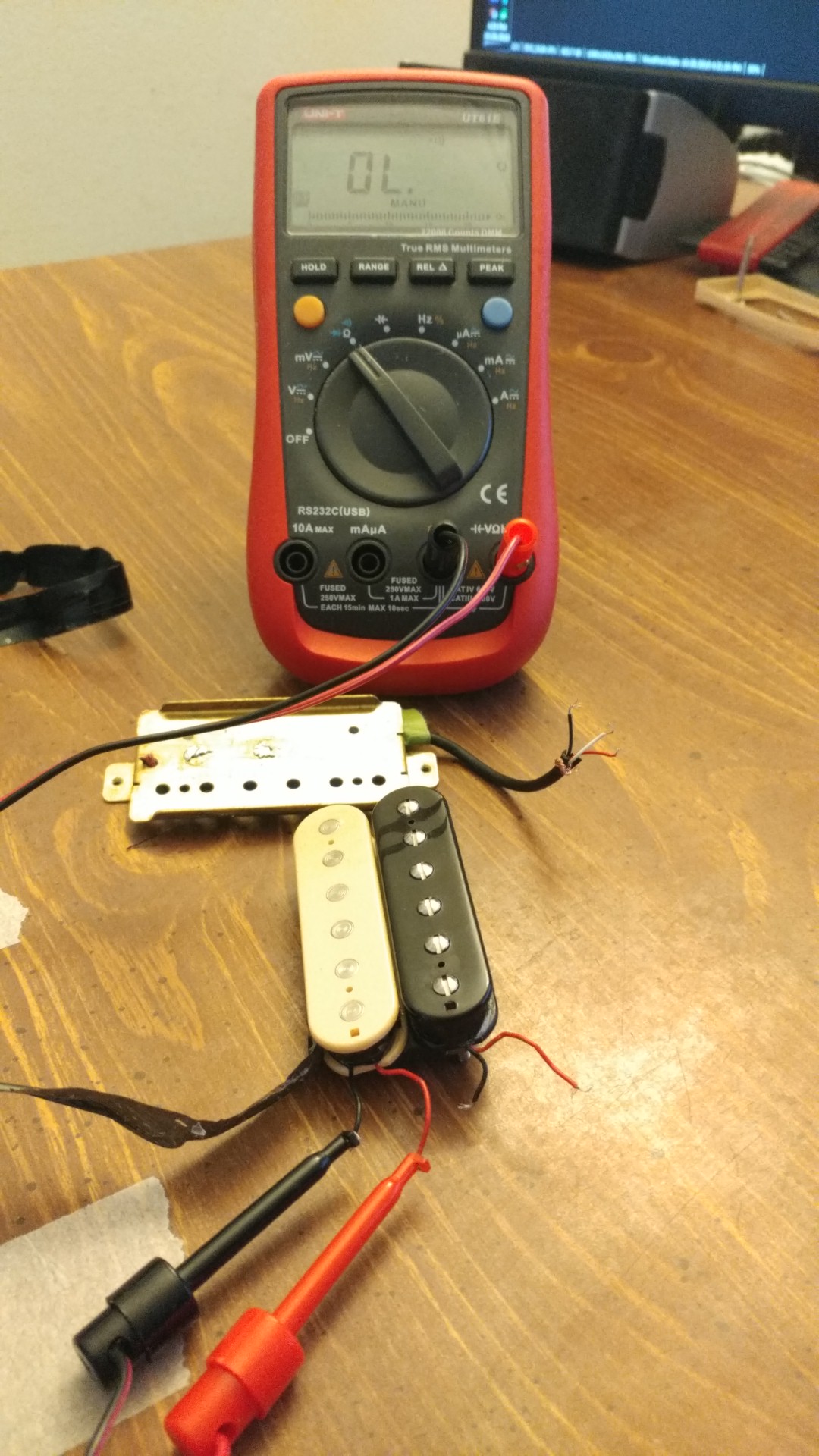
GFS pickups coloring scheme is as follows

White wire = coil split
Silver wire = Pickup Shield ground wire
Black wire = Ground
Red wire = Positive (hot)

This is pic of my rewire mod for 50s style with coil split in neck and bridge. I am unsure if this is correct and wanted to pick your brains before I proceed with rewiring job. There were few mods here. 1st was two red jumper cables were moved to middle positions in tone pots. 2nd black jumper cable was moved on neck tone cap. 3rd common ground cable was added onto volume neck pot to common ground on volume bridge pot.

48963750888_1c7f3f282f_o.jpg


This pic is original GFS wiring but this is modern style wiring and i wanted to go with 50s style so i can not go with this diagram but for reference i wanted to include it so it's easy to see how GFS wired it. I think there is also 2 errors in this pic. 1st no black jumper wire on neck tone cap and no grounding wire to common ground on neck volume tone.

48964314906_05abbf5889_o.jpg


Thank you kindly in advance
 

ReWind James

ReWind Electric Pickups Gear & Instrument Services
Double Platinum Supporting Member
Joined
Mar 11, 2009
Messages
22,065
Reaction score
39,834
Also i can not rewire those pickups for Jimmy Page style 50s wiring due to missing 5th green cable correct?


Though I've never had any here, I see posts online all over with folks talking about GFS pickups having all 5 conductors (4 wires, plus a bare ground/shield).

Some have posted replies from GFS stating they use the same color code as Duncan: https://www.tdpri.com/threads/gfs-4-wire-humbucker-color-codes.73316/

Are you sure you don't also have a bare shield/ground in there? I'd be completely shocked if you didn't.


In fact, looking at your own diagram again, you've got a key at the top left for all five conductors right on it, including the ground.
 

ReWind James

ReWind Electric Pickups Gear & Instrument Services
Double Platinum Supporting Member
Joined
Mar 11, 2009
Messages
22,065
Reaction score
39,834
Regarding the rest of your question, you're diagram is really just "half-50's" if you want to be truly correct to the way Gibson generally did it (not all vintage Gibsons are the same, so I'm talking about Bursts, in particular).

Wire your caps and pots up like this, if you want to do it the way Gibson did:
wiring50s.jpg


In the case of your coil splits - you can consider the switches completely independent from the above. Just wire like above, then use the switches to short your center tap or whichever coil you want to mute.
 

sebass

Junior Member
Joined
Mar 23, 2011
Messages
28
Reaction score
2
Yes there is 5 wire version on some, not all GFS pickups. I made a mistake and bought kwikplug version which has 4 wires coming out of kwikplug. The green wire is missing basically.

My Kwikplug has following wires:

BARE/COPPER WIRE which is maked as silver on diagram drawing = Pickup Shield ground wire

White wire = coil split

Black wire = Ground

Red wire = Positive (hot)

but is missing 5th Green wire which is seen in configuration of Standard Solder 5 leads diagram here:


If i could i would rather rewire for JP 50s Style wiring (not modern) but i'm not sure if i can without Green wire?

The pic you posted is for regular non push / pull pots and that's my current setup in my guitar as of now but i'm looking to add either coil splitters with push pull pots with replacing tone pots only or go full JP 50s style diagram with all 4 push / pull pots.

The twist to JP style is that some diagrams are modern wiring but JP had 50s style wiring which changes push/pull switch wiring positions.
 

ReWind James

ReWind Electric Pickups Gear & Instrument Services
Double Platinum Supporting Member
Joined
Mar 11, 2009
Messages
22,065
Reaction score
39,834
Sorry to hear about the lack of a proper 4+ ground wiring on your pickups. If you're electrical skill set is up for tackling building a harness like the Page / 21 tone setup, you should have no problem modifying your pickup's wiring to use a full 4 + ground setup. If you don't mod the pickups, you can't do the series switching and can't do the 21 tone harness.

If you just want to do coil splits, follow my instructions and the diagram I posted: Wire up like the 50's diagram and use the switches on the push/pulls to do your coil splitting (explained in the text under the diagram I posted). The fact that your tone pots have switches on the back of them doesn't change how the 50's wiring works.

....or just use the diagram you posted. It probably won't sound / feel much different, anyway. You've got the whole tone circuit on the switch lug, just the pot before the cap, rather than the traditional cap before pot.


The twist to JP style is that some diagrams are modern wiring but JP had 50s style wiring which changes push/pull switch wiring positions.

How do you know if Page had 50's wiring, once all those switches were put in? I have never seen a photo of the guts of that original guitar. If you've seen one, please do share a link. That's would be really interesting to see.

btw - perhaps you already know this, but it's always worth mentioning, even if only for future readers - Jimmy Page never had any of those switches installed during the time of Led Zeppelin. Those were put in after, when he was in The Firm. Many people stop caring about the switches altogether, after realizing that. Most Page fans are interested in the Zeppelin sound.
 

sebass

Junior Member
Joined
Mar 23, 2011
Messages
28
Reaction score
2
So correct me if I am wrong but is the ground wire in the kwikplug itself and then soldered onto back of the pickup plate.
However kwikplug itself has actual bare/ground wire coming out of it.

I see 2 black wires and 2 white wires. I'm assuming blacks are negative from coils and 2 white are positive from pickup coils. If you look at the GFS instructions below it appears to be the case.

My plug is the last one identified with 4 conductor vinyl lead.

Looks like i need to create ground wire but what is the best place to originate it from?

Obviously i will measure which coils is which and color code it to SD color scheme once identified. Will probably need colored cables too.

Would that be correct?

Thank you and much appreciate your help.

48968960812_588d6ab1b6_o.jpg


48968960862_3f5f08afba_o.jpg


48968239353_bf4ae32b46_o.jpg


48968928491_e8b1bb9ddf_o.jpg


48968515888_97590b4a51_o.jpg
 
Last edited:

ReWind James

ReWind Electric Pickups Gear & Instrument Services
Double Platinum Supporting Member
Joined
Mar 11, 2009
Messages
22,065
Reaction score
39,834
No, it isn't the ground you are missing. You have a ground. It looks like you have only one conductor going to both coils that they are calling "coil split." This is how the original DiMarzio Dual Sound pickups were wired up, before they realized that was a terrible idea and switched to a full four conductor + ground wiring.

GFS pickups are about the absolute cheapest pickups that one can obtain, including used. So cheap, it's amazing they can make them and run a website to sell them on. It's no surprise that they use a poor design, which is poorly implemented, and poorly documented. They must cut corners everywhere.

If you want to mod the pickups to be four conductor + ground, you need to identity each of the coil starts and finishes and attach them and your chassis ground to a new hookup lead. The lead you posted a photo of won't work.

Be careful, as the little black and white leads that connect to the fine coil wire are guaranteed to not be secured well and that fine coil wire they attach to can break about as easy as a human hair, if it gets tugged on a little. The repair cost to rewind a single coil is more than that whole GFS pickup costs new so if you aren't confident don't do it.
 

sebass

Junior Member
Joined
Mar 23, 2011
Messages
28
Reaction score
2
So instead of guessing i've decide to take the pickup apart and ditched the kwikplug. Now this is NOT the neck i posted above with black and white wires but bridge pickup so wire colors have changed. Sorry about that. So here it is. How do i wire TO SEMOUR DUNCAN DIAGRAM to bridge red and black colors in this pic. Please igonore pic above. Again sorry about that.

So there is red (positive?) and black (negative?) [ASSUMPTION] coming out of each coil. 4 wires woo hoo. 1 to go.

Now i've done continuity testing on kwikplug and the bare ground wire coming out Kwikplug plug is connected to pickup shield housing on the kwikplug housing which is soldiered onto housing therefore that is the GROUND AND FINAL 5TH WIRE so i think?

Now to create that mysterious 5th i think (please correct me if i wrong) but i need to soldier the bare/ground wire out of pickup housing and run it out as bare 5th wire therefor creating the 5th WIREEEEEEEEEEEEEEE

YES?

If there is better spot to avoid short were would it be or is pickup shield ideal spot to originate pickup bare/ground wire from?

I will be wiring this according to SD diagram color scheme. How do i test with DMM which is the start coil wire and end coil wire IF in some weird case black is not ground and red is NOT hot/positive. That would super weird but i need to make sure cause as we know the wiring on later is precise.

Also when i when i ran continuity on red and black wire there was NONE? There shouldn't NO continuity between positive and negative correct? I think not but i would rather ask.

Does the coil of the pickup always start with POSITIVE and ends with NEGATIVE?

Thank you again for help.

GFS taken apart. 4 total wires.

DSC_0182 by Sefyu, on Flickr

Resitance test on single coil. 7.2k. Both coils are supposte to be 14k which equates.

DSC_0180 by Sefyu, on Flickr

Continuity tests between positive and negative wire

DSC_0181 by Sefyu, on Flickr

Back of pickup. No bare/ground wire anywhere i can see here!!! ???

DSC_0179 by Sefyu, on Flickr

The wring color scheme i will be going with

Capture by Sefyu, on Flickr
 
Last edited:

ReWind James

ReWind Electric Pickups Gear & Instrument Services
Double Platinum Supporting Member
Joined
Mar 11, 2009
Messages
22,065
Reaction score
39,834
There is no positive or negative lead on a pickup coil. Red and black are just arbitrary colors. The output signal is AC so both leads are both positive and negative, alternating with the signal.

I don't think there is a simple way to determine start/finish of a coil on a DMM. There's a way you can make a good guess with an old analog needle meter but DMMs aren't fast enough to do that.

Since those pickups use the Chinese bobbins with the end of the flange nipped off and no hole on the underside to pass the start wire through, they are wired up with both leads soldered to the outside of the coil, making determining start/finish pretty difficult, short of taking the coil tape off and seeing which lead hooks to the start of the coil that passes under the rest of it.
 

sebass

Junior Member
Joined
Mar 23, 2011
Messages
28
Reaction score
2
Thank you sir. So when i test with DMM for polarity and have knob selected on mV, the lowest possible voltage curent.

I tap each coil with metal screw driver to activate magnet so it would generate mV curent.

This is what DMM is showing me when DMM positive and negative leads are connected to the wires.

Based on what i'm going to say below. Which is start and end of each coil ?

I'm going to be soldering SD colored wires onto each one of those cables but it's CRITICAL star and ends are correct.

GFS Crunch Pat (Bridge 14k)
Screw Coil -- Red wire - Positive DMM reading

Screw Coil – Black wire - Negative DMM reading

Slug Coil – Red wire – Negative DMM reading

Slug Coil – Black wire - Positive DMM reading

GFS Vintage 59 (Neck 8.0k)
Screw Coil -White wire – Positive DMM reading

Screw Coil -Black wire – Negative DMM reading

Slug Coil - White wire – Negative DMM reading

Slug Coil -- Black wire – Positive DMM reading
 
Last edited:

drryan

Junior Member
Joined
Aug 15, 2021
Messages
1
Reaction score
0
Just registered so I can say thank you for your diagram. It helped me a lot. The GFS one is not correct as you identified previously. I was able to get the GFS Surf 180s wired up for dual coil splitting with your dg. With gratitude, ryan.
 

Attachments

  • 20210815_101833.jpg
    20210815_101833.jpg
    75.9 KB · Views: 101

Latest Threads


Top
')